
If you have not already installed your magazine, please follow the instructions in Magazine Installation to install your magazine and move your spindle into the correct reference position before continuing.
Run Test Script
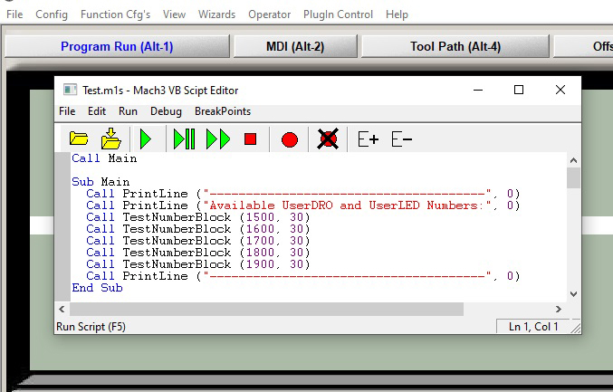
RapidChange requires 30 User DRO’s and LED’s for our Mach3 scripts and screen set. To avoid having conflicts with third party plug-ins and screen sets, we have a test script that will confirm a section of DRO’s available in your Mach3 install.
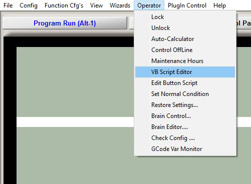
Download the DRO test script and open the Mach3 VB Script Editor.
From the Script Editor, open the DROTest.m1s file that you just downloaded.
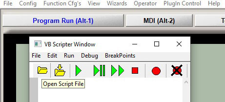
Click the green play button to run the script.
Click on the History button.
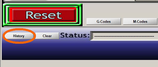
You should notice some output flashing in the status line as the script runs. After it has completed, open the status history and scroll to the bottom of the text file.
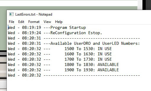
Choose a range that is available and download the appropriate RapidChangeMach3.zip file here . In this example I will be using 1800 to 1830.
Install the Screen Set
Find the file you just downloaded.
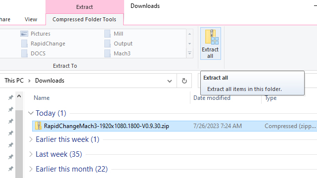
Click extract all.
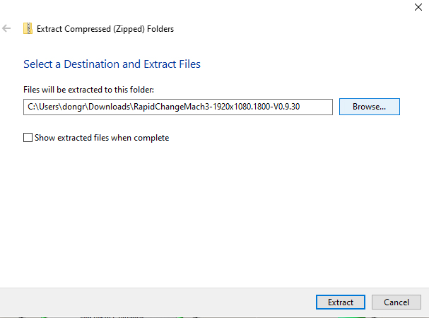
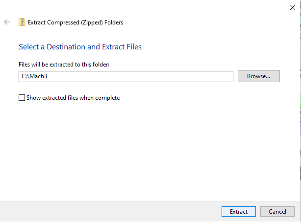
Select the Mach3 folder
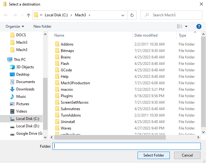
Click Extract
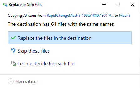
Make sure to replace all files.
Configure Mach3
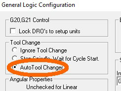
Open Mach3, then open the Config tab, then click on General Config… and make sure Auto Tool Changer button is active.
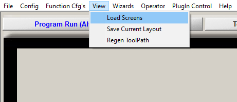
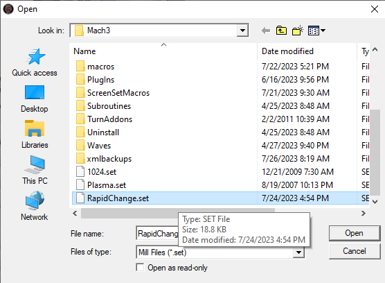
Load the RapidChange screen set named RapidChange.set.
Tester Version of Mach3
The rest of this article is outdated please go to the video section and watch the video it will cover most of what is in here.
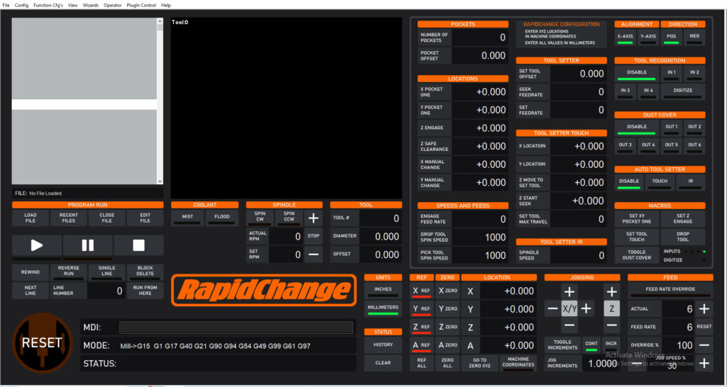
Set the Number of Pockets and Pocket Offset. Here I will choose 5 pockets and 38mm for pocket offset for an ER11-mini magazine. The specific offset will be provided with your magazine.

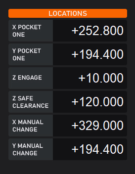
Next input the Machine coordinates you found in Getting Started as well as your safe clearance height. If your machine is at Z engage height and positioned in the first pocket, you can click Set XY Pocket One and Set Z Pocket One buttons in the Macros area of the screen.
In this example the tool setter is outside of the magazine so the distance from pocket 1 to the center of the tool setter will have to be measured. If you have a tool setter pocket in your magazine. The center will be the same distance from the first pocket as the pocket offset and you can simply add or subtract from the pocket 1 location along the axis on which the magazine is aligned.
X and Y Manual Change location can be where ever you want the machine to go if the tool recognition is triggered by failing to drop the tool. In this example we will have it share the tool setter position.
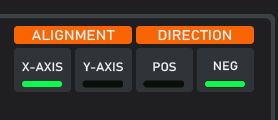
We will use this ER11-mini magazine as our example. As shown in the picture below we have an external tool setter. The spindle is shown hovering over pocket one. The magazine is aligned along the X axis. Pocket is 2 is -38mm from pocket one.
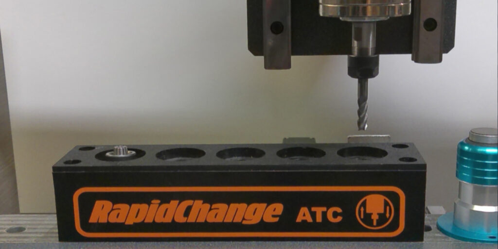
So we will set the alignment and direction DROs like this.
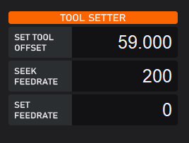
Set Up the Tool Setter.
Set Tool Offset is the distance from the tool setter to the top of the table bed, or the bottom of the work piece. This value will have to be calibrated to match your needs. Set the Seek Feedrate, this is the speed the spindle will move down to touch off. Set Feedrate, currently we only support a single tap tool setting function, however we plan to implement a double tap if possible, at which time the Set Feedrate will be used. At this time it is unavailable.
Enter the machine coordinates of the tool setter.
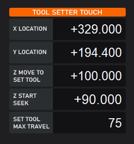
Z Move to Set Tool height should clear any tools in the magazine. Z Seek Start is the position that Z will begin the probing sequence. Set Tool Max Travel is the maximum distance the spindle will travel down in Z to touch off.
Tool setter IR
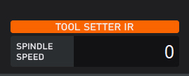
This would be the spindle speed for using the IR break beam as a tool setter as it comes up out of the pocket. This is a feature we are sill working on.
Tool Recognition
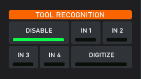
If your magazine came with IR sensors you will need to select the input for the sensor here. If your magazine did not come with IR sensors leave disabled.
Dust Cover
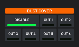
If your magazine came with a dust cover you will need to select the output for the signal to the external logic board. Running the dust cover on an axis in Mach3 is coming in the next couple days. If your magazine did not come with the dust cover leave disabled.
Macro Buttons
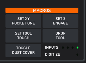
While setting up the magazine or if you need adjust the positions. Set XY Pocket One, will set the pocket one DROs to the current machine position. Likewise with the Set Z Engage.
Set Tool Touch will probe the current tool in the spindle.
Drop Tool will drop the current tool in the spindle.
Toggle Dust Cover with open and close the dust cover.
The LEDs are for visually checking that the tool setter and IR sensors are functioning properly.
Feeds and Speeds
Lets set the spindle speed and feet rate for your tool changes.
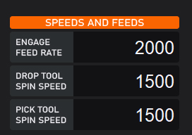
A good place to start with ER11 is what you seen shown above the top recommended spindle speeds for ER11 is 2000rpm and 2500mm per min. For ER20 This would be the upper recommended limit for spindle speed and should achieve 10-14 ft. lbs. depending on the clamping nut you are using I have found Maritool’s standard clamping nuts to produce the best clamping torque. I have tested the ball bearing version and it did not perform as well. Maritool clamping nuts will achieve 3-4 ft. lbs more than the standard inexpensive nuts sold on Ebay and Amazon.
The feed rate will always be faster than the spindle speed. what you want to look for, is that as the spindle is threading the clamping nut. The nut should not appear to move up or down in the pocket. It is recommended that acceleration be set to 200 and Z max velocity should be at least 2500mm per min.
Make a Tool Change
If your tool is still in the spindle from getting started make sure that tool one is shown to be in the spindle.
You can click the Drop Tool macro button. The spindle will move to safe clearance, then to X and Y, open the dust cover if your magazine is equipped and configured to the correct output pin. and drop the tool moving back to safe clearance and stopping.
Make certain of your movement clearances and in the MDI type: M6 T1 click enter and the machine will pick up tool one and move to set the tool length unless you have it disabled.
If you encounter chatter you are either missing a bearing or not low enough in the pocket at the engagement height. If you it hear rubbing or the action had a lot of noise then realign X and or Y so that rubbing does not occur.