
Dust Cover Controller
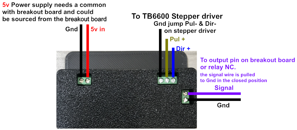
The Dust Cover Interface operates on 5v power.
In the diagram below the signal (Purple) and common (Black) wires will open the dust cover when completing a circuit. In other words when the signal wire is pulled to ground the dust cover opens. This allows for wiring various switching devices in parallel. Allowing a wide range of choices for control.
Examples:
A rocker switch could be utilized that opens the dust cover for manual control.
An NPN proximity sensor or a N.O. mechanical limit switch could be mounted on an axis to open the dust cover when the spindle moves into position over the magazine.
An output or relay on the motion controller will activate the dust cover during the M6 call with integrated motion control software.
IR Sensor
Wiring the sensor is easy.
Connect the black wire to ground and the red wire directly to 3.3V or 5V power. It will draw 9mA from 3.3V (lower power) and 20mA from 5V (better range) and then the green wire to your digital input. You must have a common gnd from the IR sensor to the motion controller. The receiver is open collector which means that you do need a pull up resistor. Most microcontrollers have the ability to turn on a built in pull up resistor. If you do not, connect a 10K resistor between the green wire of the receiver and the red wire.
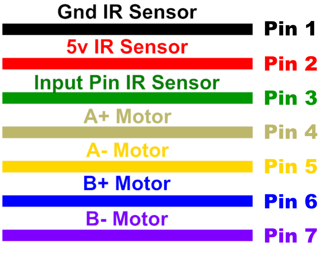
Cable Legend
The following colors and pin outs for the cable and GX16 8 pin connector using 7 pins
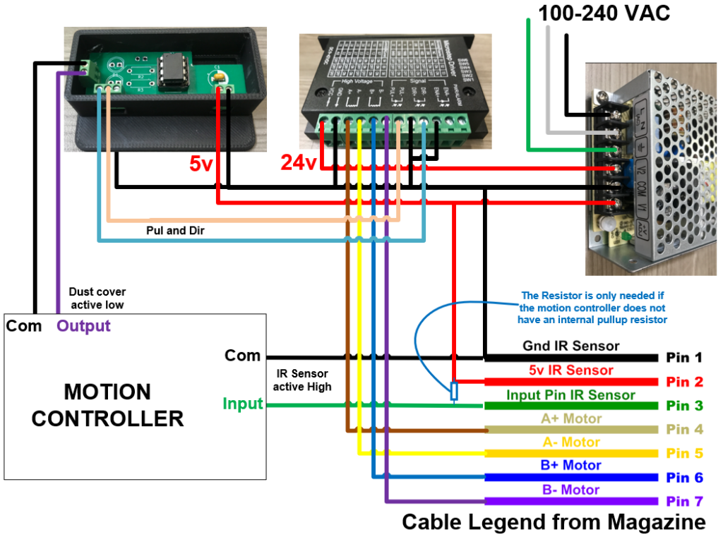
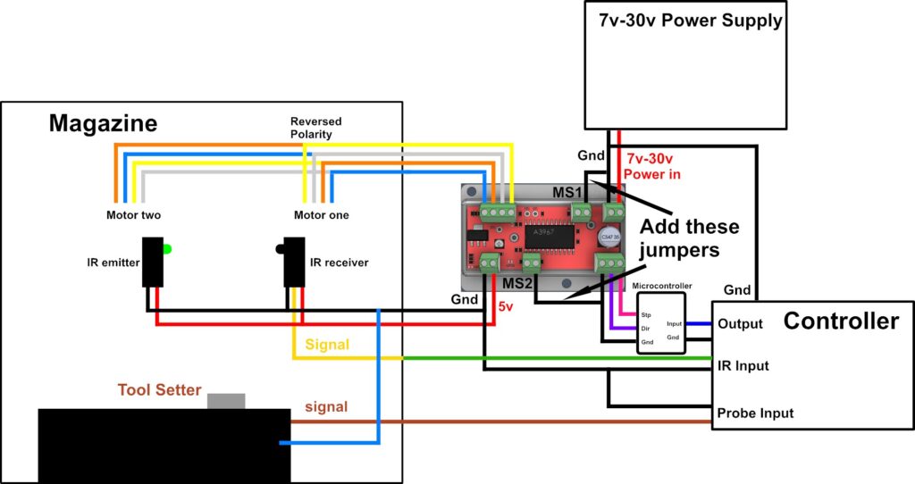
Wiring Diagram for Output Control
Obsolete Wiring
The first batch of magazines shipped with the 8 conductor cable connected to the wiring harness in the magazine. We stopped doing this because the tool setter and IR sensor share one wire and depending on the motion controller this will be either the ground or 5v.
Connected Cable
If your magazine came with a connected 8 conductor Shielded cable, the following is the legend:
Blue orange white and yellow connect to the easy driver.
Black and red are for ground and 5v source from the easy driver.
Green is the signal wire from the IR sensor.
Brown is one half of the tool setter circuit normally open it shares the Gnd with the IR sensor. With certain controllers this will need to be switched and share the 5v with the IR sensor or add an independent conductor.
MS1 and MS2 microstepping pins are pulled to ground for full stepping and best torque.
Axis Wiring Diagram
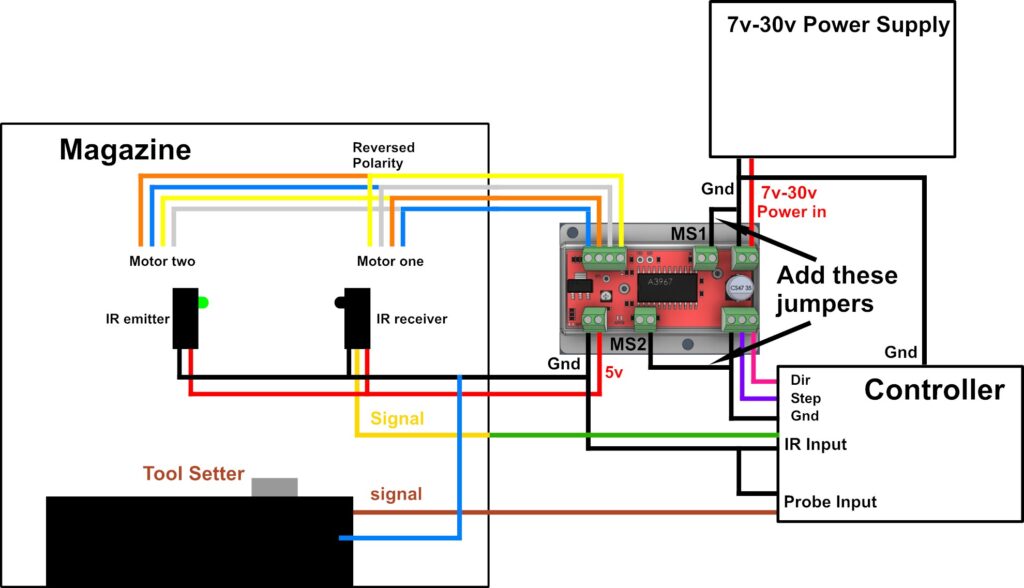
Microcontroller Wiring Diagram
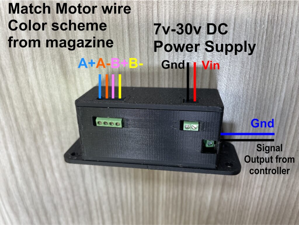
Prototype Microcontroller Stepper Driver Combo
The 7v-30v can be sourced from the motion controller itself or the power supply driving it.
Unconnected Cable
The Magazine now comes with a separate 8 conductor Shielded cable. The photo below shows the connections that need to be made between the cable and the pigtails in the motor housing. you can use this legend with the diagrams above.
Magazine Wiring Harness Legend
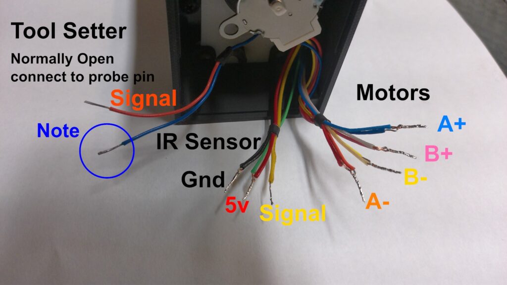
Note
There are 9 wires coming from the wiring harness in the stepper motor housing. one of the tool setter wires must tie into either the 5v or ground wires connected to the IR sensor, depending on the motion control board being used. Some controller inputs are wired for common grounds and some for common voltages.
For example: With FluidNC set up running on Bart Dring’s 6 pack controller. The IR sensor and Tool Setter share the ground. With a UC300ETH board the IR sensor and Tool Setter share the 5 volts.