
How was the idea for this automatic tool change system conceived, compared to traditional pneumatic systems?
The initial idea wasn’t to create an automatic tool changer. The goal was simply to organize cutters and avoid losing wrenches. After building a prototype and realizing the torque it produced, the potential for an automatic tool changer became apparent.
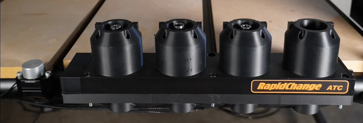
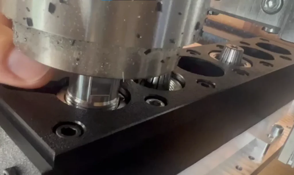
How's the Magic happen?
The system works on the principle that the spindle’s mass and rotational force, upon hitting a stop, cause the tool to tighten.
Our ATC mechanism utilizes the spindle’s rotational force for tool clamping and unclamping, ensuring precise and reliable operation.
Tool Holder Design:
It uses a specially designed tool holder with a socket that has limited contact points. An initial hexagon socket caused jamming, leading to the development of a three-point contact system, and eventually, ball bearings. This design prevents jamming and minimizes wear on the clamping nuts
Clamping (Tightening):
As the spindle descends, the clamping nut, which is prevented from rotating, encounters a hard stop. The slight initial resistance during threading allows the spindle to briefly move upward. This upward deflection enables the spindle to regain rotational speed before plunging down again. With each plunge, the rotational inertia of the spindle shaft applies torque against the hard stop, progressively tightening the nut onto the collet. This process ensures a secure and precise clamp on the tool.
Unclamping (Loosening):
For unloading, the clamping nut is designed to deflect downward. As the spindle ascends, the spring within the mechanism allows the bearings to align with three sides of the nut. The controlled deflection and spindle’s rotation then efficiently loosen the nut.
Optimizing Spindle Speed:
To preserve the mechanism’s integrity and ensure optimal operation, we recommend tightening around 1500 RPM & loosening at 1600 RPM. The generated torque is comparable to hand-tightening with wrenches. The spindle RPMs are critical, as higher RPMs (e.g., 2,000+ RPMs) can damage the socket.
Is RapidChange ATC compatible with my system?
We strive to make RapidChange ATC compatible with as many platforms as possible. There are many “Boxed” CNC machines available with their own proprietary controls that are very limited in what they can do with custom macros and spindle control. Our recommendation for determining the compatibility of a machine falling into this category is to contact the manufacturer and ask them these questions:
- Can I create custom macros? Particularly M6?
- Can I run the spindle counter-clockwise with G-code?
- Can the spindle be programmed to run at a minimum of 500rpm?
RapidChange ATC Magazine offers more than 10 integration packages. Upon purchase of a magazine customers are given access to all of the current and future resources that we have available for integrating with your machine.


What are the requirements I might not be thinking of to set this up?
Make that your CNC machine meets the necessary requirements, including being accurate and reliable.
The spindle must be able to run in reverse (counter-clockwise).
Make sure you have adequate power and the control is capable of sending the necessary commands.
Consider the space and accessibility for the ATC magazine to operate seamlessly.
What is the recommend speed to tight & loosen the collet nut?
We recommend tightening around 1500 RPM & loosening at 1600 RPM.
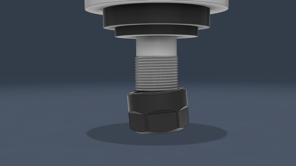
Can this really generate enough torque to secure the cutter?
Absolutely- check out these videos of cutting steel and aluminum with the RapidChange ATC.
The generated torque is comparable to hand-tightening with wrenches.
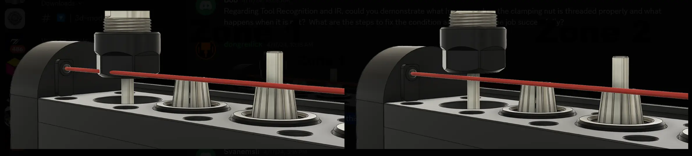
What about cross-threading?
Our system simply doesn’t create enough torque to cross-thread a hardened spindle.
ACTUALLY cross threading the hardened steel of the spindle would require EXTREME torque, far beyond the 14 foot pounds that our system delivers. The only potential problem is for the nut to become stuck at the start of the threading process. The ONLY way this could possibly happen would be through GROSS MISALIGNMENT where the spindle shaft is NOT perpendicular to the magazine. (see image at right)
That said, alignment is critical, and any misalignment can cause the collet nut not to thread completely on (or at all). Our IR sensor is really handy for this.

Won't this damage the spindle over time?
The spindle running under load at low RPM will cause it to get too hot but the few seconds it runs to load and unload the collet is no problem.
I ran loading and unloading cycles for 6 hours one day including over 1500 tool changes with no significant wear or spindle overheating. The spindle didn’t even get as warm as it does during a normal cutting job.
Do the parts wear out?
The main components, including the caps and bodies, are made from High-Density Polyethylene (HDPE).
For the sockets, we conducted extensive testing and chose 3D printed ABS for its superior durability. Unlike other materials like PC/CF, which crumbled under stress, our ABS sockets are engineered to absorb shock, ensuring reliable performance.
While they are built to withstand normal use, they can experience wear or fail with excessive RPMs or impact. Because we stand by their design, we offer a lifetime guarantee on all sockets. If a socket wears out, we’ll either send you a replacement or, for users with a 3D printer, we’ll send you the STL file so you can print your own and get back to work without delay.
Are replacement parts available?
Yes, absolutely. We provide verified owners with the CAD files so you can print a replacement and get back to work immediately.
As part of our lifetime guarantee, we will also ship you a replacement socket at no cost.
Are drawings available to check mounting constrains?
Our Discord has 3D models of every available size magazine offered on our website. These are simple objects but include pass through holes for the tool pockets as well as the mounting holes so the models can be used for mounting patterns.
We recently adjusted the width of all the magazines from 54mm to 60mm.
The models all have the housings (end caps) included so just delete them if you are only looking for a Base Magazine setup.
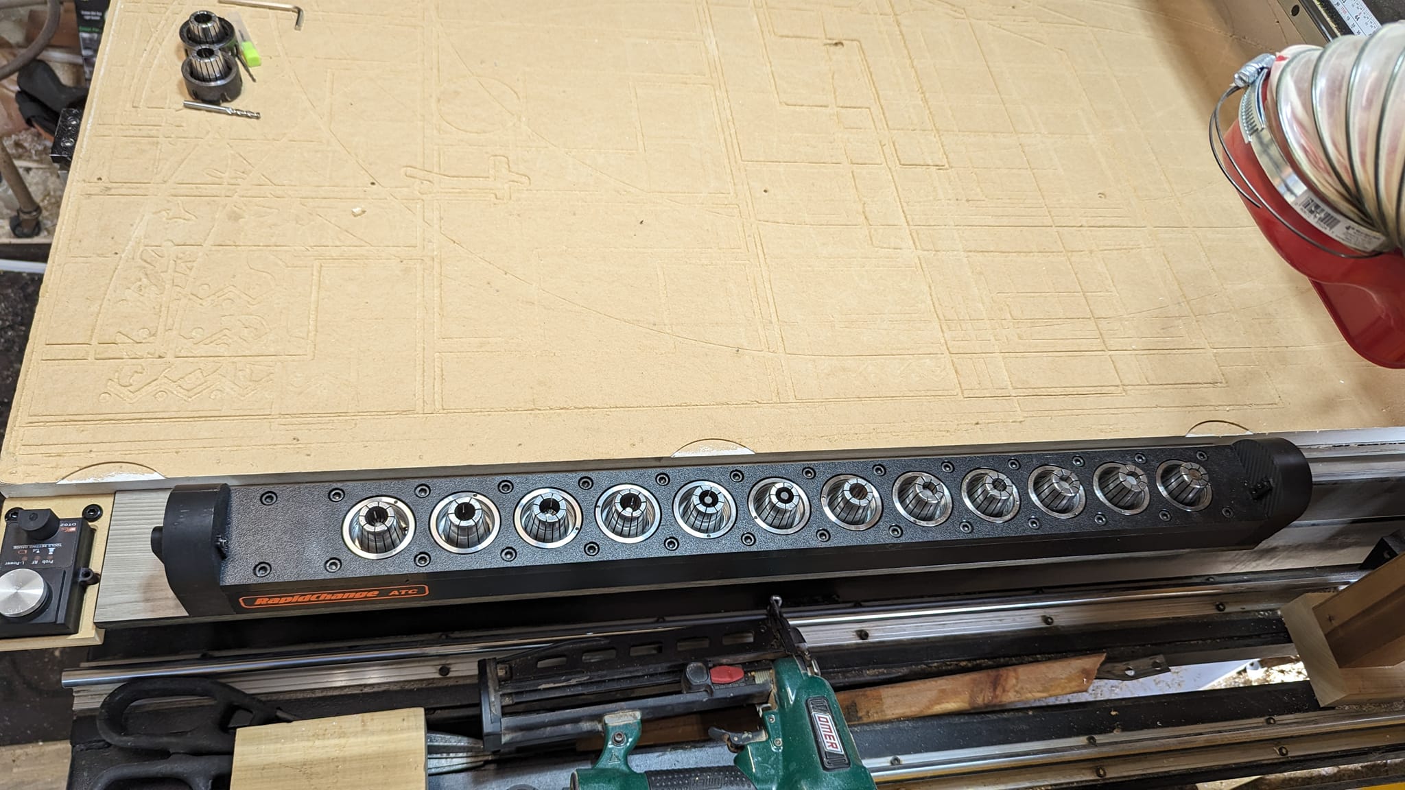
Can I get more than 8 sockets?
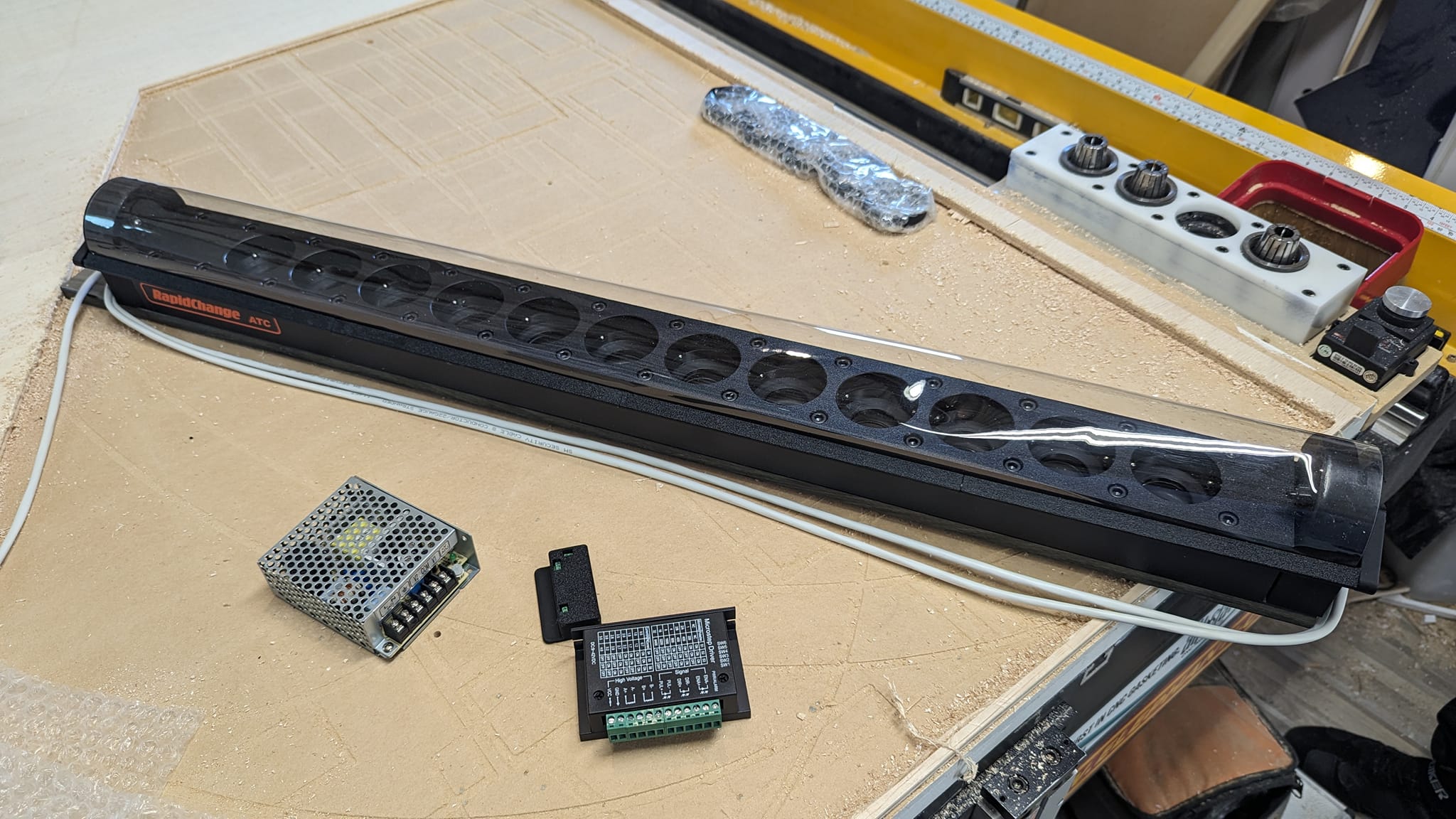
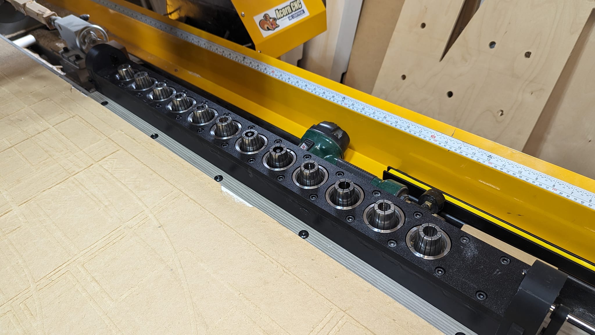
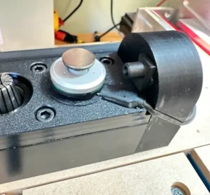
What's the physical setup process look like?
The unit comes with mounting templates. Users bolt it to their table, locate the first pocket, and configure the software. The cable connector is an aviation connector with seven pins for the infrared sensor and stepper motor.
How much Z axis clearance do I need?
90 mm Z axis clearance is needed to position the magazine on the machine bed without being inset.
Is magazine alignment really that important?
Yes, misalignment of more than 0.2mm will cause the threading process to become unstable. That’s just .008 of an inch – the thickness of a human hair.
RapidChange works as well as your CNC machine. Your machine will have to be repeatable. In other words, missed steps will cause misalignment. If you have closed looped steppers you will not have this problem.
For tool changes, you should have a highly repeatable process, which is independent of how precise it is. Endstops for example are not precise, but they are extremely repeatable if you approach them at the same vector.
First, align the magazine to the desired axis, then align the spindle to the magazine sockets.
The videos below share some tricks I’ve learned along the way.
My machine keeps getting out of alignment with the RapidChange ATC. What can I do?
Dual gantry systems are very good at getting out of square, causing the misalignment that you may not have seen yet. This can happen for multiple reasons, the most important ones being open loop steppers running too fast or accelerating too fast. But it happens for a more practical reason as well: a lot of (frequently used) cheap TB6600 drivers out there are unreliable and will just miss steps during normal operations, which will cause this misalignment in an hour or less.
There’s a simple solution: add an optional homing cycle before using your tool changer (before every change). Or even better: g53 g0 x0y0 and then $H home x,y. If the g0 fails and runs into an endstop, it’s out of square and will alarm; normally it will just home without a change. Closed loop users won’t need it, it’s only required for open loop systems. That will render cross threading virtually impossible in most cases.
Also, the CNC system itself should arguably alarm if a homing cycle doesn’t return to zero, because it’s an indication of a bigger problem.
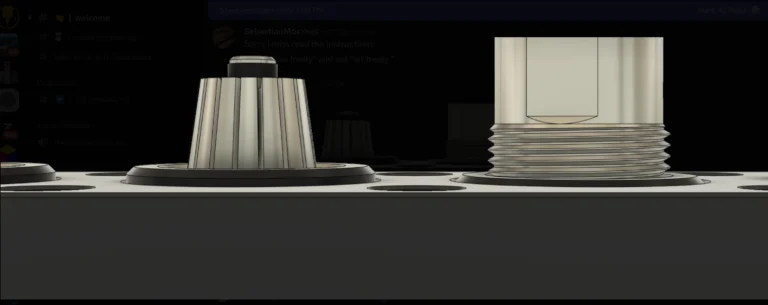
I'm setting the Z height. What do you mean, it should "sit freely?"
With a tool and collet in the spindle the nut should sit at the same height as it would if it was just sitting in the pocket.
It’s important that you have a collet and tool in the spindle when you do this otherwise the nut will spin up onto the shaft too far.

Bring the spindle down into Pocket 1 to a position just below where it would sit freely. Now lower the spindle another 0.5mm just to make sure the nut is seated all the way down in the socket. This will be your Z engage Height.

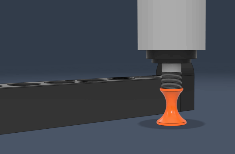
Can you explain the Z "Engage Height?"
This step determines the lowest point the spindle will move in Z during the process and helps to find that location so when positioned like in the rendering below, the Z machine coordinate will be Z Engage.

What's your top pick for a motion controller system?

If setting up another machine, Centroid would likely be the choice due to its robustness and features.
How can I run my spindle at such low rpms?
There are generally two steps.
First, VFD parameters need to be modified. I don’t have a comprehensive list of the various VFD parameters, but the video below covers setting up the popular Huanyang and USB RS485. (Spoiler- it is PD011=0 and PD073 = 0.)
Second, the easiest way is to run a VFD is through a USB RS485. It works with many controllers, including Mach3, UCCNC and FluidNC, is easy to set up and it’s only two wires. The RS485 is inexpensive, has been around for over a decade and is very reliable.
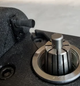
How does the IR safety sensor work?
When dropping a tool, the system checks if the beam is blocked (indicating the nut is still in the pocket). If blocked, it attempts to drop it again; if it fails a second time, the program pauses.
When loading a tool, it checks if the beam is blocked (nut on spindle) and then clear (nut threaded properly). If the nut gets stuck and does not thread correctly, it blocks the beam, triggering a fault and the program pauses.
A fully tightened collet nut clears the IR beam and the program continues without user interaction.

Why isn't the IR sensor recognizing the loaded tool?
Sometimes the IR sensor can be overwhelmed by light from a window or even bright shop lights.
If you have any trouble, a couple of our creative users came up with some easy solutions.
The quick & dirty solution is to add a piece of shrink wrap tube over the dark IR receiver to narrow the allowed light a piece of shrink wrap tube over the dark IR receiver to narrow the allowed light.
The second is a 3D printed cover which has a small tab on each side for a drop of superglue to hold it to the case.


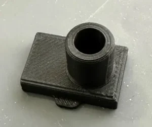
Do I really need the dust cover and IR sensors?
I believe they provide a more autonomous workflow. Without them more monitoring is required.
That said, our magazines will speed up your workflow in any configuration!
I thought collet nuts were standardized. Why should I measure mine for compatibility?
I assumed the same thing, but unfortunately encountered significant variations in collet nut dimensions that can impact the performance and fit of our ATC sockets – particularly with ER16 collets. To avoid potential issues, we strongly recommend measuring your collet nut’s dimensions before placing your order for a RapidChange magazine.
Please refer to the infographic below to confirm if your collet nut matches one of our compatible sizes.
If yours doesn’t quite match, we can often help with alternatives, but it works best if your collet nut is one of the sizes shown.

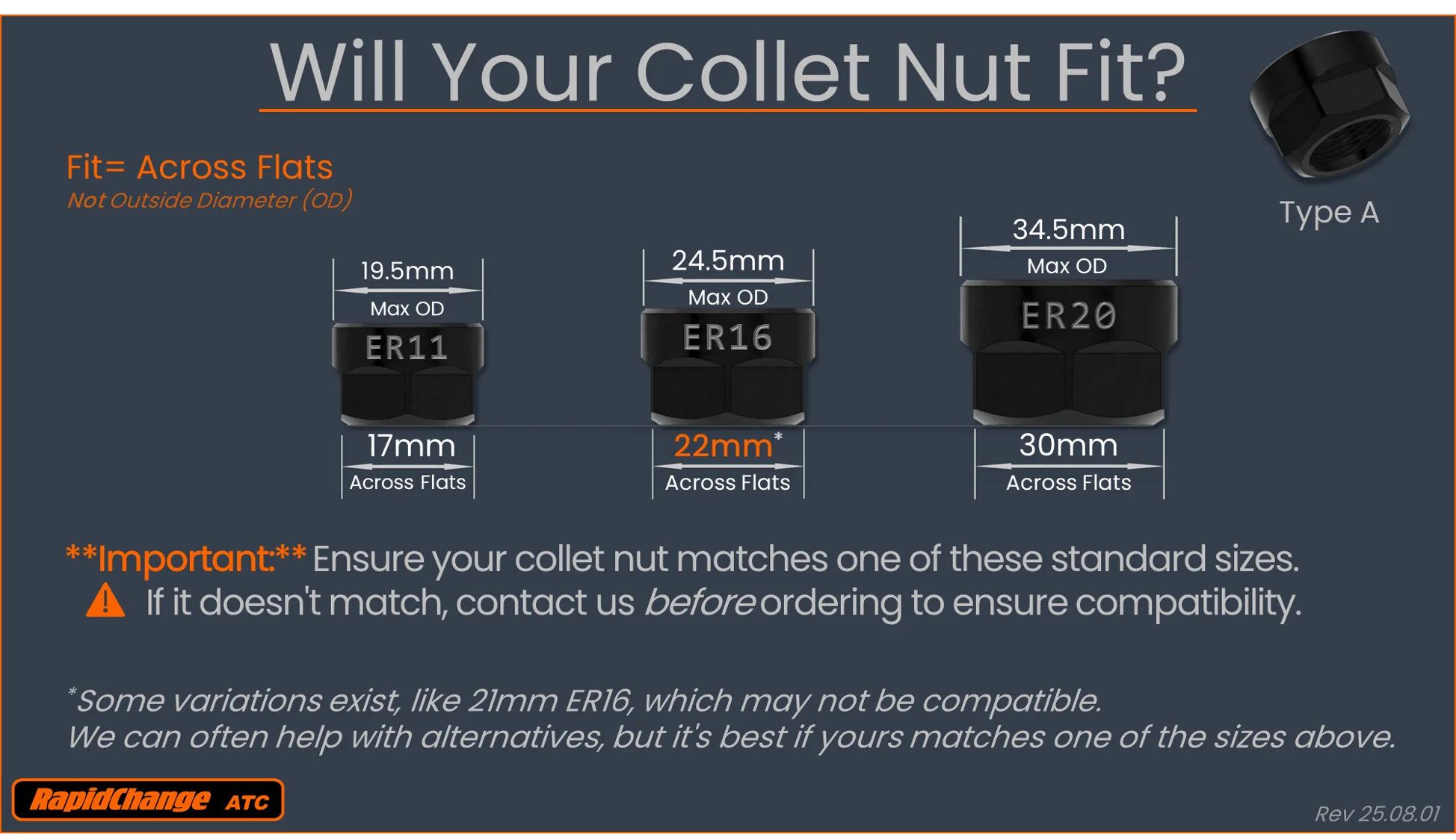
Should I use Type A collet Nut or a Type UM?
There is no functional difference, but I would go with the A type just because it’s more common.
When you get to ER25 and above the Hex (Type A) style is not available.
Why do some of my tools slip out of my collet?
Sometimes the metal has internal stress, and when the slits are cut into the collets for expansion, the stress is relieved, causing the holes to open up a bit more.
How can I prevent the tools from slipping in the collet while in the magazine?
I prefer to have a snug fitting collet if possible, but there are a number of solutions.
- We sell Collet Shields (disks) to combat this.
- I used heat shrink tubing for a while.
- Some users report that O-rings or orthodontic rubber bands, like for braces, work well.
- MariTool sells collets that have an O-ring in them that can help.
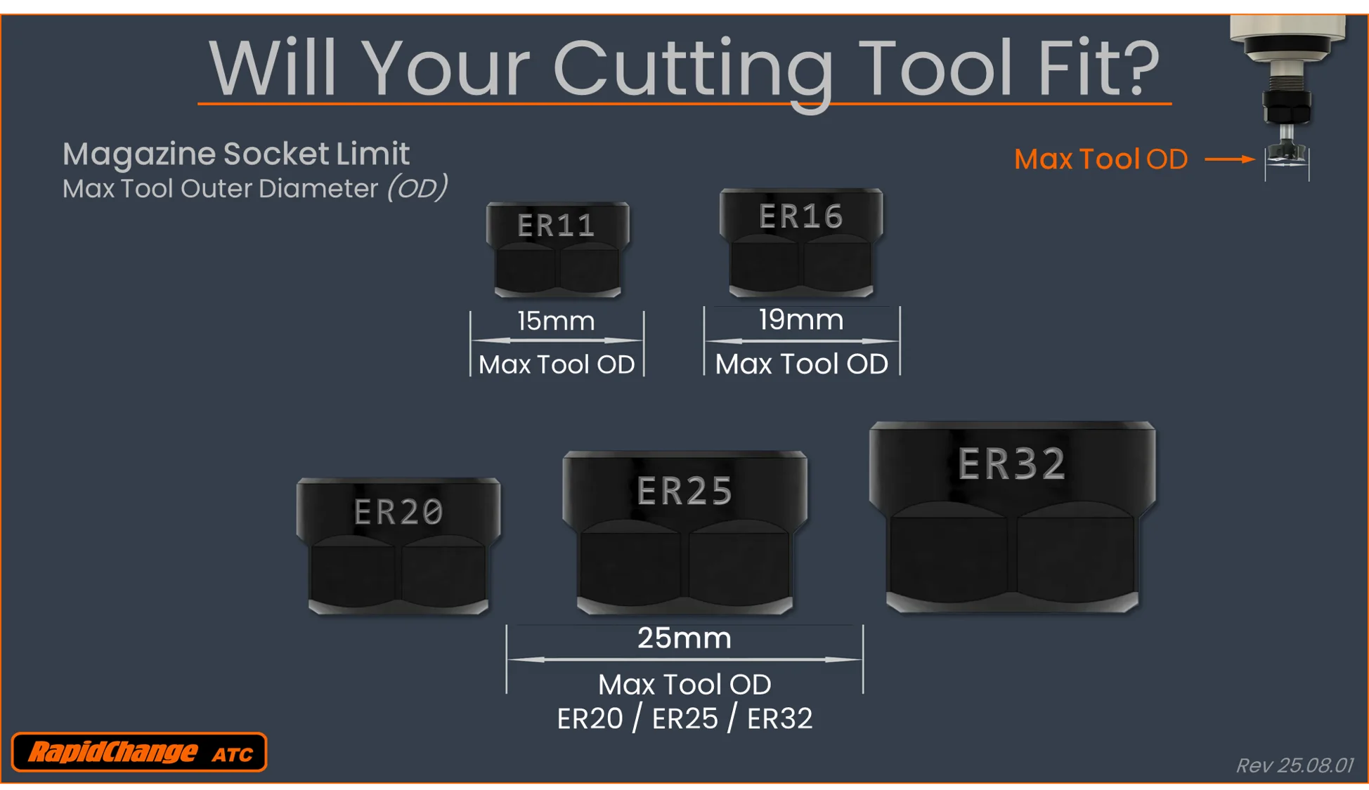
What's the maximum tool diameter?
Our current specs for Max Tool OD to fit in the magazine are:
ER11: 15mm
ER16: 19mm
ER20/25/32: 25mm

What's the max tool length?
The limit on “stick out length” is dictated by the clearance above and below the magazine.
The RapidChange ATC Magazine allows the tool to pass through the bottom and accommodates approximately 24mm of stick out without a riser or recess beneath the tool pocket.
We provide CAD files with the layouts and geometry for users to make their own riser blocks.
Can I change collet sizes later?
The ER11, ER16, and ER20 all have the same geometry- the only difference is the sockets. Contact us to order new sockets.
Can I upgrade the magazine later?
The systems are modular, so the IR sensor and Dust Cover system can be added later.
Fusion 360 for personal use has limitations regarding tool changes and rapid movements. What can I do?
Yes, Fusion 360’s personal use license (hobbyist version) has a couple of key limitations that affect CNC machining, especially when using multiple tools:
- No Automatic Tool Changes: Removing automatic tool changes means the inability to post operations that use more than one tool. Posting multiple operations is still available, so long as they all use the same tool. This means that if the program uses multiple tools, each section has to be an individual post.
However, if the program uses multiple tools, you typically need to post each toolpath individually and manage tool changes manually at your machine. - Reduced Rapid Feedrates: All rapid (G0) movements, including those between operations and during simulated tool changes, are reduced to the cutting feedrate. This significantly increases machining time compared to the full commercial version.
Fortunately, the hobbyist community has developed a solution, and Tim Paterson has shared his Fusion360-Batch-Post add-in on GitHub. The add-in fixes some of the limitations of Fusion for Personal Use by allowing you to batch post-process multiple setups with tool changes for your atc, and it can help restore proper rapid movements.
It requires editing the post processor (details in the GitHub repo), but reportedly works great after that. Once configured, simply create your tooling with appropriate tool numbers, create your setups in Fustion 360, then run the plugin.
While we’re happy to share the information about this valuable add-in, please be aware that we cannot provide tech support for this. We encourage you to explore the add-in’s documentation, and feel free to ask around in our Discord community to see if other members can offer assistance or share their experiences.
My magazine doesn't look the same as the new ones. What's going on?
We’re constantly improving. Old magazines were 54mm wide, including the kits (which are no longer sold).
The dust covers have gone through many iterations and improvements. For a while we used stepper motors, but are now using servos.
Can I buy the Onefinity Tower-Style magazine?
The Onefinity “Tower Style” linear magazine is designed to provide room for the dust boot to straddle the tool sockets during a tool change. There are sensors for each tool location, as the boot blocks the beam otherwise.
They are not on the website, but contact us for availability.

Are there plans for a turret system?
A turret system is in development, though the current focus is on increasing awareness and establishing the existing system. A turret would involve a circular arrangement of pockets that rotates to position the tool.
Check out our prototype in the videos below.
Can I change motion controllers later?
Yes, this is simply a software change and is independent of the hardware side of the RapidChange ATC.
Just like when the unit is first purchased, we can configure (or re-configure) your Web Portal for any of the supported motion controllers.